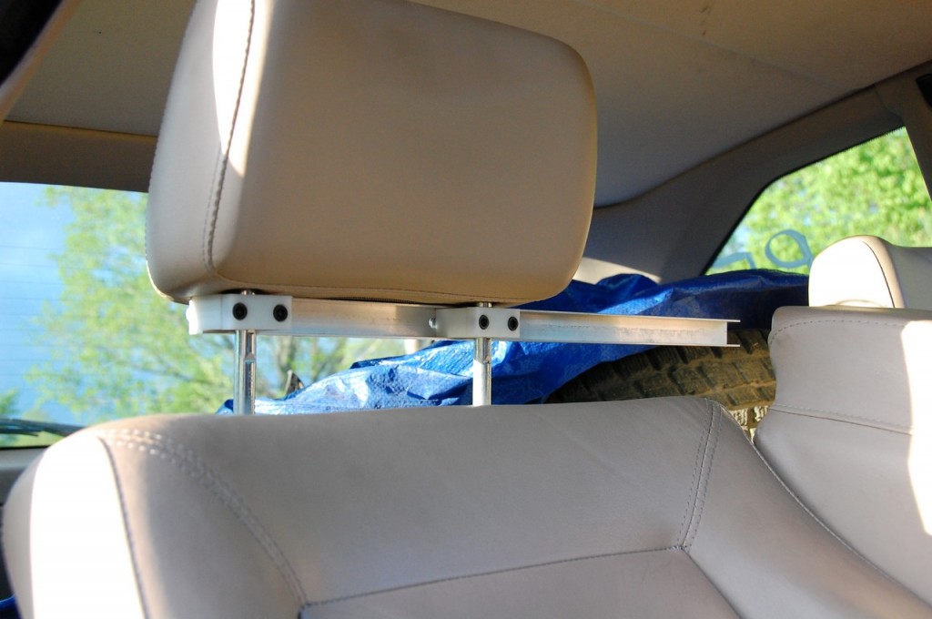
Now that the machine is here, I decided to do a small project to start my way up the learning curve. For a while I’ve been planning to build a camera mount for our rallycross car so that we can capture some footage of our events. I happened to spy a neat design on someone’s car at a recent event – it clamped to the headrest posts and extended towards the center of the car to provide a spot for the camera. It looked easy enough to copy and modify to suit my needs, and it occurred to me that it would be a fun project to get my feet wet on the new machine.
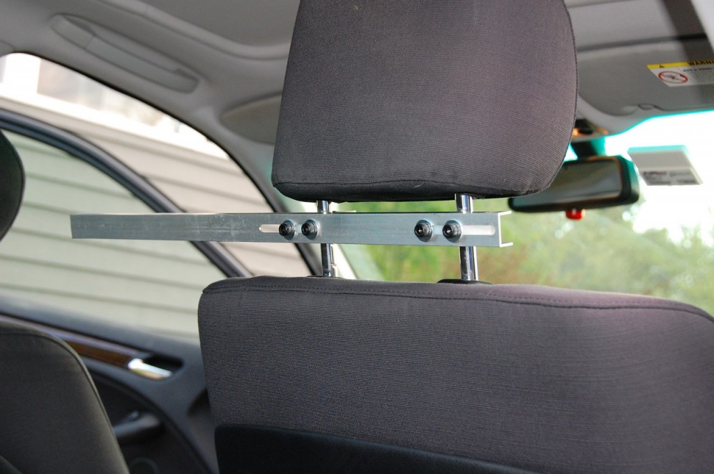
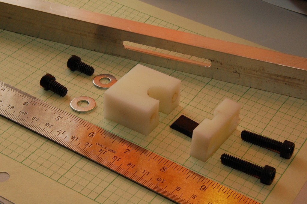
Digging through the “useful materials” scrap bin I’ve been building up over the years, I found a big chunk of nylon which would be well-suited to clamping blocks, and some aluminum C channel. I designed on-the-fly and I think I’ve got a decent start. Still need to work on a simple articulated camera mount and probably re-doing one of the clamp blocks which bore the brunt of my rookie machining mistakes.
I did a test fit-up in the two cars it was designed to fit (the clamps are adjustable) and it seems to be quite stable. Should hold a camera quite steadily, subject to the stability of the seat itself. Hopefully it’ll help to produce some watchable video!
[Editor’s Note: We quickly abandoned this as it was deemed far too unsafe to run in a vehicle. But it was still a fun machining project.]
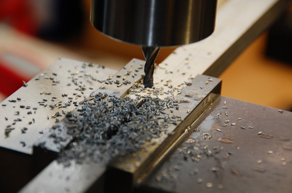
Overall I’m finding that I really enjoy machining. The precision of the machine is quite a revelation. Until now I had done all of my half-ass mechanical work using pretty low end stuff like drill presses, hack saws, files, and a lot of eyeballing and rough measurements. To have basically produced a small assembly actually using math and counting on the measurement capabilites of the machine and to have it work and turn out well is really quite a thrill. That much of it turned out within good tolerances (+/- .001 in many cases) gives me hope for when I actually get good at it.
Using the machine manually is a bit of a chore, especially keeping track of turns of the dial. However, it does give me a basis of appreciation for what it will be like when the machine is under CNC and I can run it in semi-manual mode with a pendant. In essence, much of the tedious wheel-jockeying should be reduced. Shuttling the bed to a particular coordinate where I want to perform a milling or drilling operation will be as easy as typing it in. Executing simple stuff like milling channels, pockets, circles, etc., will all be fairly easy. And that’s all before it gets really fancy with CAM software, taking CAD drawings and churning out parts with hopefully ever-decreasing tedious tasks. The future looks bright!