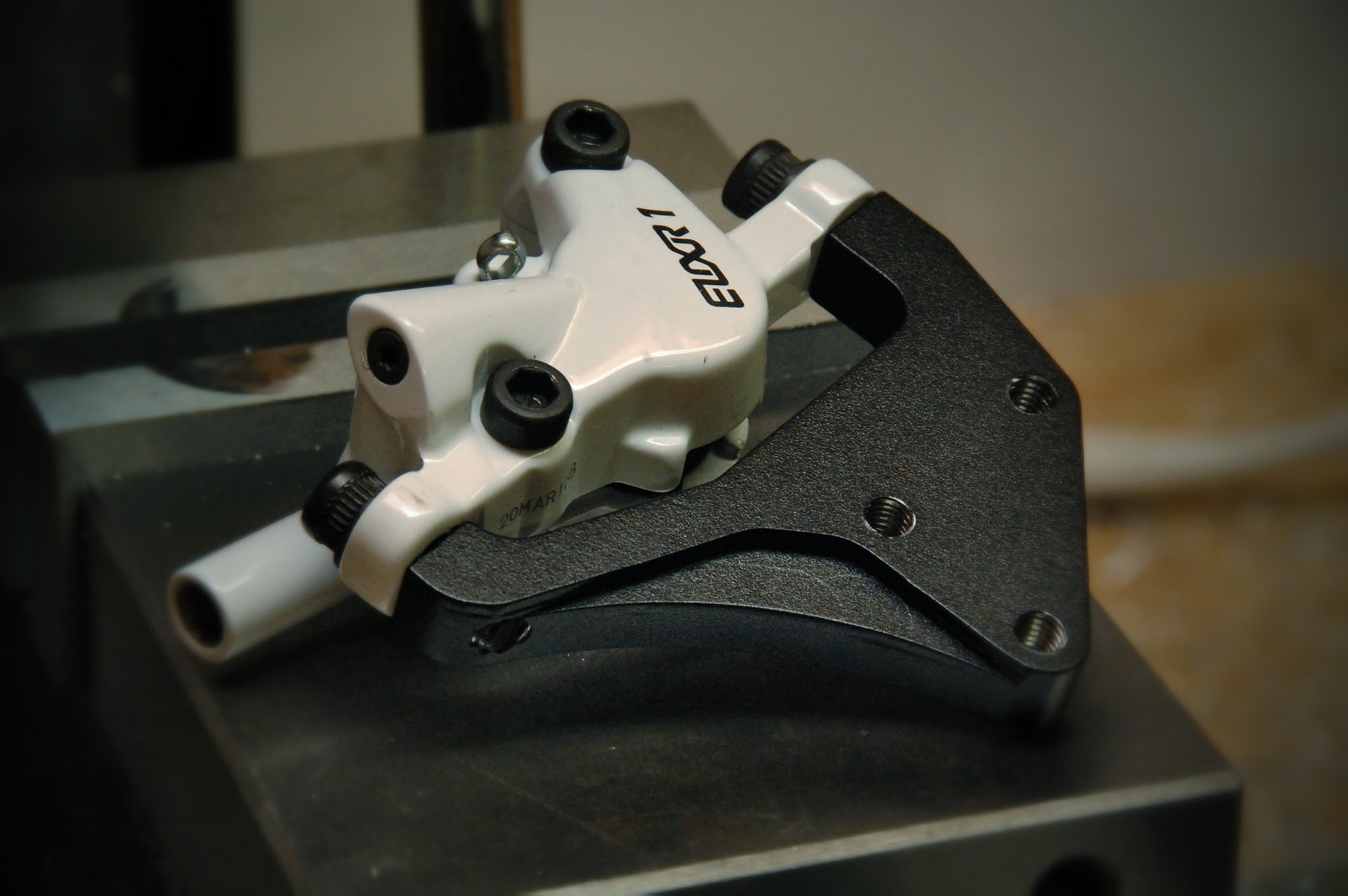
Bicycle Disc Brake Caliper Mount
[ngg src=”galleries” ids=”11″ sortorder=”140,141,134,135,136,137,138,139″ display=”basic_slideshow”]It’s no secret that I can get pretty wrapped up in projects. Witness a “small” project that I took on for a friend,…
Measuring with Software
Every so often you may need to measure something small and inconvenient. Specifications with physical dimensions may not be available to you, so you need to actually…
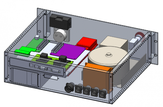
10lbs of Junk in a 5lb Box?
I’ve been slowly working to model the components that go into the CNC milling machine electronics package, and fitting them into an off-the-shelf rack mount enclosure. I…
Shaking off the Rust
It’s been a long, long time since I’ve done a PC board layout. Like, probably on the order of ten years. I think I may have done…
Pelican Case Motorcycle Luggage Project – Part 4
I made the other locking mechanism for the other piece of luggage this weekend and I made a little video showing some of the CNC process, as…
Custom Droid Car Dock
[singlepic id=237 w=320 h=240 float=right] My passion for in-car tunes goes back well over ten years, with the a half-finished (but functional) automotive MP3 player that could…
Pelican Case Motorcycle Luggage Project – Part 2
[singlepic id=208 w=240] In a big push to get the Pelican luggage attached to the bike before a trip to the Delaware Water Gap, I spent a…
Pelican Case Motorcycle Luggage Project – Part 1
[singlepic id=200 w=320] [singlepic id=205 w=320] The cramped cockpit and limited cargo options of my Kawasaki Ninja EX500 weren’t going to suit my long-term desires for a…