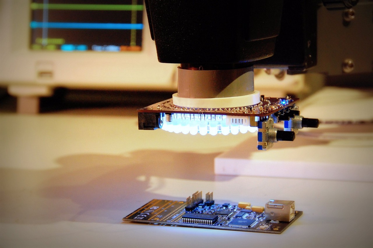
In an earlier post back at the beginning of this month, I described the beginnings of my DIY microscope illuminator project, dubbed Project AZIZ. At that point I had just sent the PCB off to OSHPark for fabrication. I’m happy to report that in the weeks since, I not only received the boards back, but I’ve built the first prototype and written the first revision of firmware!
The assembly and bring-up of the first prototype went quite smoothly, with only one minor error on the board that was easily fixed by bodging in a pull-up resistor. Working with the Atmel ATTiny1634 micro proved to be a relatively painless experience, using the Atmel Studio IDE and the affordable AVR Dragon debug/ISP interface. Even soldering the QFN MLF-20 package that I chose for the microcontroller was not a big deal.
I put together an in-depth video showing all of the features that are in the firmware, some actual footage of it in use (captured by my microscope camera output), as well as some highlights of the assembly process. Check it out below!
I decided to release the firmware as open source, under the Mozilla Public License 2.0. Check out the AZIZ portfolio page if you’d like the GitHub link.
Without kits available to the general public, I realize that releasing the firmware is of limited use, but maybe someone will find it useful. Along those lines, I am interested to hear if anyone would like to build their own, either as a full or partial kit. The design as it stands would need some DFM and cost improvements before releasing it to the world, but it’s certainly something I am considering if there is some interest.
[ngg src=”galleries” ids=”9″ display=”basic_slideshow”]
I loved your project, and I’m very impressed by all of the thought that you put into it.
Having said that, if you decide to make a second generation, I have a few tips (as a photographer, with 20 years plus of experience) on how you can make it better and get much less glare.
Example: the LEDS that are non-frosted should be on the outside, should stand out a little farther then the frosted LEDS, and should be pointed inwards (past the center point) That way, one of the modes should be to only illuminate two non-frosted LEDs, one opposite of the other.
Again…amazing idea. Great execution.
Thanks for the compliment and suggestions. One of my friends called dibs on one of my extra boards, so perhaps I’ll ask him to build it up using your suggestions to see if there’s improvement in performance.
-Steve
Steve,
Great work! Would love to talk to you some more on this project and add my two cents on the human factors part, e.g. the knob interfaces. I have some ideas and possibly some better LED choices out there. Shoot me an email and let’s talk. Worst case, I would buy a kit off of you yesterday!
for some reason, when I play your video, after 5 sec into it, it gets interrupted by very annoying commercial for some wishlist app on iphone. Try it out. It was annoying beyond believe.
Strange, it does not do that for me on any of my desktop browsers or my smartphone browser.
Nice work. Very professional. Good idea. Still seemed that the contrast was bit low, but likely due to the grey ink on black package.
I can also suggest the Maxim MAX6969 to drive the LEDs. SPI interface makes it simple to use – I have made a 64 LED sign for the back of my motorcycle driven by an Artuino. That LED driver chip is sweet.
The camera I used for the demo is also low quality, and it has its own contrast issues. I’m sure that didn’t help.
Good job! We have made some very basic led ringlights for our stereo microscopes (only on and off) but I always wanted something like your aziz! Will you sell the pcb seperate? Or make the gerber and bom open source too 😉
Nice work.. Which software did you use for drawing the pcb?
I don’t find hardware files.
I just put the schematic up in PDF form in the GitHub repository. I know it’s not the complete design, but it’s still useful.
Steve,
Any chance of getting the pcb files in an editable format? I embarked on a similar project a few weeks before I saw this, and just might steal, er appropriate, er, copy your great design!
I really just want to adjust the size to fit my microscope. 🙂
Very impressive work on your ring light. I regularly perform microscopy on printed security features for product packaging, and I think my own lab would benefit from a production model of your ring light if and when it becomes commercially available.
This rules, very nice. What kind of microscope do you use? I need one for my home lab!
It’s an old Bausch & Lomb StereoZoom that I picked up used on ebay.
Awesome project Steve. I’ve been planning a project similar to this but it would have RGB leds and allow you to configure the color for use with Full Spectrum Video and Digital Cameras. This inspired me with lots of ideas. Thanks so much for sharing!
-Dave-
ZOMG the Fifth Element reference is so awesome.
Absolutely stunning work Steve!! I also use OSHpark for my PCB, even though I am based in Europe. After weeks of research on the Net, I picked it up for a try and now I am hooked to it! It’s the best PCB printing service around really (and I also love the solder mask). I stumbled across you page as I am struggling with an Arduino implementation of a couple of TLC59116 to drive three stupid 7 segment LEDs for my uncle (he wants a huge pool thermometer using common anode 4in LED digits). Apparently no-one has ever done such a stupid design using these TLCs!! I like to make things funny, and if possible, PWMed! No useful code is on the net except yours and another dodgy LED lights project (some fancy LED lights for a shop). Your code is superb in comparison. The other project is absolutely terrible in terms of syntax and logic. I spent all night trying to figure out how they soft cabled the appliance deep inside a dedicated library. You couldn’t do worse for code re-usability! So I will try to adapt your code to my project, even though I am not quite certain to know how to inject it into the Arduino IDE. If you have any advice, that’d be wonderful as I expect to spend quite some time banging my head on my keyboard in the days to come!! All this is quite tough as it’s my first “real” MCU project but I am a fast learner… Keep on the good work and thanks for sharing it with us!!
I’m interested. If you ever do another run of boards, or indeed put together a kit, put me down for one. Thanks.
I really admire the amount of work putted in development of this project. Very useful. Is there any chance that you will publish technical drawing of the broad or CAD files?
Jakub
Great project. I’d like to make something similar for the microscope at work. What are the specific LEDs that you used?
They were purchased from two different Chinese ebay vendors, and they were not packaged with any useful information like part numbers, nor with data sheets.
Great project! Would it be possible to make it available as a kit? Maybe through kickstarter? Regards, Jeroen
Fantastic job on this! I’d love to adapt this pcb for a project I’m working on, is there any chance I can get gerbers for this? Or have another copy manufactured through OSHpark? It’s nearly exactly what I need, and if I could avoid having to go through the effort of laying out a PCB I certainly would appreciate it!
Dear Steve,
I read all the articles and reviews of AZIS and I am determined to do it. Unfortunately I have not enough knowledge and experience to compile and run the software on the microcontroller Atmel ATTiny1634, so I’d like to know, if it is possible to send me an email with the *.BIN files and detailed drawings of the whole PCB’s.
Thanks for Your reply, best regards !
Bogdan
Steve-
I am very interested, and would purchasing
several as either only boards, boards with parts,
already assembled, or completely packaged.
Please consider making the board available.
thanks and regards,
-Jim
I’m very impressive with your work.
I would like to buid one but don’t know how to read the schematics could you please public the PCB design? I think it was easy this way.
Thank you
Paulo Costa
Amazing work Steve !!!! Can you please share the hardware design for the same. I really want to work on this idea.
Hi Steve,
Great project !
Would you agree to send me the gerber files ? I’d like to order a PCB from OSHpark to build one for me.
Cheers
Hi Steve,
I’m building a home brew microscope for soldering use and came across your project. Do you have any boards for sale for the AZIZ ring light? If not, is it possible to buy a copy of the artwork / PCB files from you so I can get a set fabricated?
I’m a radio ham, and new to playing with small surface mount. Eyes are suffering, but have a couple of SDR projects to build.
Any help appreciated. Cheers, Ian
I read all the articles and reviews of AZIS and I am determined to do it. Unfortunately I have not enough knowledge and experience to compile and run the software on the microcontroller Atmel ATTiny1634, so I’d like to know, if it is possible to send me an email with the *.BIN files and detailed drawings of the whole PCB’s.
RY3GWD@YANDEX.RU