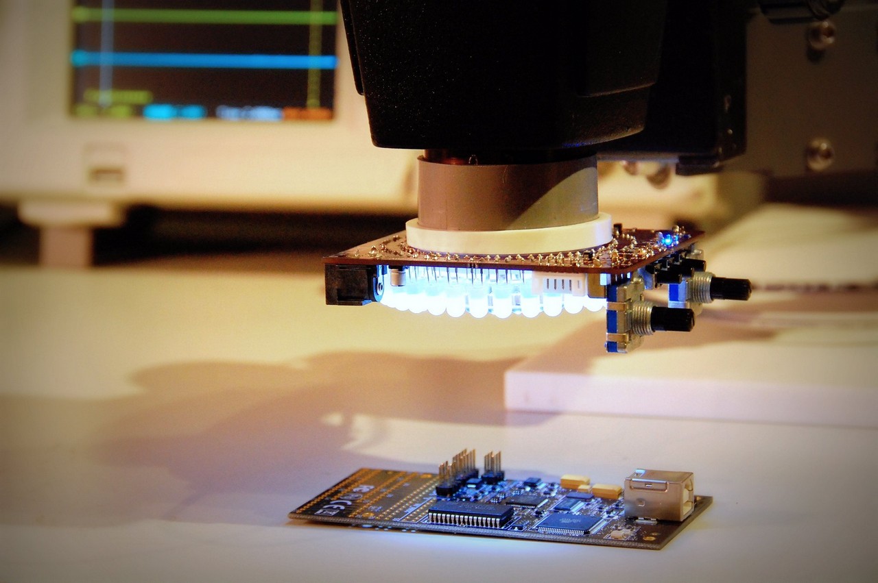
My recent acquisition of a stereo microscope for the electronics lab has brought about a couple of side-projects. One of them is the custom boom stand that I built a couple of weeks ago. Another is this custom LED ring light, which I’ve dubbed Project Aziz (named after the poor kid holding the mirror from The Fifth Element). The design features 64 white 5mm LEDs in two rings. The inner ring is intended to be populated with super high brightness (25,000mcd) water-clear LEDs with a narrow projection angle. The outer ring will get reasonably bright 6000mcd diffused white LEDs. The LEDs are driven in groups of four, splitting up the circle into 45 degree wedges. The LEDs are driven by a TI TLC59116 constant current LED driver chip with 16 individual channels.
The LED driver chip is connected to an Atmel ATTiny1634 AVR microcontroller. Two rotary encoder knobs, three buttons and three LEDs all connect to the microcontroller as well, providing a simple yet powerful user interface. The firmware is not yet written, but I’m planning to provide controls for brightness as well as pattern selection and rotation. Mixing between the spotlight and diffuse LEDs may also turn out to be useful. This may sound like overkill (and it may well be), but I have found it pretty valuable to be able to vary the lighting patterns and brightness to help get the best visual contrast with objects viewed under the stereoscope.
Given that the design by nature is donut-shaped, there was a bunch of PCB area in the middle that would have otherwise gone to waste. After fretting for a couple days over what to include, I decided on a breakout for these tiny OLED displays I picked up last year. I included a switching boost converter design for the 12V OLED drive voltage as well. The rear of the board has a simple pad breakout for the same ATTiny microcontroller I used on the ring light, in case I run into difficulties with programming/debugging the microcontroller on the main ring light design.
I’ve been working on the electronics design and PCB layout during the last couple of weeks, and I just sent out the board to be fabricated at the excellent OSHPark (formerly Laen’s PCB order). I’ve run a handful of designs through them and I’ve been extremely pleased with the results. The experience has only improved with the addition of a web-based design submission system that gives you excellent visual feedback of the files you’ve submitted. Highly recommended. More news in a couple weeks when I receive the boards, and I populate them and bring them up!


Looks great, but why through hole LEDs?
I used TH LEDs to keep the option open of bending them to aim towards the center of the ring. I have a commercial ring light on my microscope at work, and all of the LEDs are installed at an angle. If it turns out this is unnecessary perhaps I’ll do a version in the future which is all SMD.
I also had bought a bunch of them, thinking I was going to just wire something up on perfboard, before I decided to do a PCB. So it was also partly a matter of designing to what I had on hand.
Great stuff!
I hope you don’t mind that I referenced your work with the stereomicroscope in a project I run to make (neuro)science more open and affordable. It is at http://openeuroscience.wordpress.com/hardware-projects/microscopy-hardware/stereo-microscope-the-steve-richardson-way/
Let me know if this is alright!
Best regards.
Hi,
Could you share HW manufacturing files? It would be nice to have this tool on my desk 🙂
All the best,
Fryco