It occurred to me that not everyone may have any idea what an opto interrupter is and does.
Opto interrupters are small sensors, used to detect the presence or an absence of an object. The sensors are typically U shaped, and contain an infrared LED and a phototransistor responsive in the infrared band. Phototransistors are like regular transistors, but the base has been replaced by the light input, thus the current flow through the transistor is controlled by light. Simply put, this makes it a sort of light-controlled switch.
Phototransistors are inherently analog devices, however, and their outputs do not “snap” between on and off crisply. There are variants available with signal conditioning internally (typically Schmitt-trigger type outputs), which provide a digital output making interface to digital circuits easier. This is done with thresholding, e.g., if the voltage is above a certain level, it is considered a 1, and if below, a 0. Typically this conditioning also has a dead band in it so if the signal is very close to the threshold level it will not oscillate between states. This type of conditioning can also be done externally, as I did for my home switches in the CNC mill.
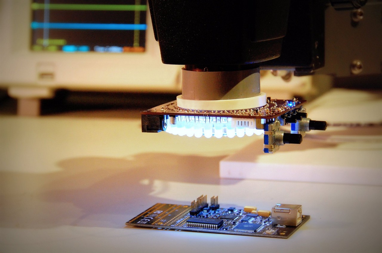
I made a quick video which shows the behavior of an opto interrupter. The LED is driven at about 16mA, with a 5V supply and a 300 ohm current limiting resistor. The phototransistor has its emitter tied to ground, and the collector pulled up through 2.2K ohms to 5V. The oscilloscope probe is connected to the collector. You can very clearly see the analog behavior as I slowly move the object in and out of the sensor.
[youtube -N6KS2LhfVE]