 Every so often you may need to measure something small and inconvenient. Specifications with physical dimensions may not be available to you, so you need to actually measure the item you have at your disposal. For example, if you want to experiment with a harvested electronic component and put it onto your own PCB, you need to create a footprint. While patience and beer go a long way to helping you make footprints, what you really need are measurements.
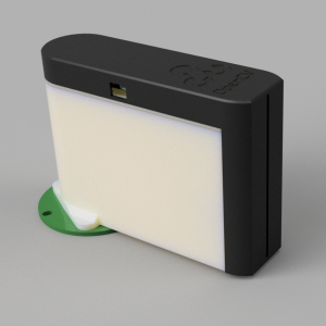
Let’s say you have removed a component as shown on the right. This happens to be the IR tracking camera from a Nintendo Wii controller. Measuring the footprint on the original circuit board would be very handy, since it’s known to fit the part.
 Measuring the actual holes in the PCB (or the pins of the component) with calipers is challenging to do accurately. However, measuring the overall width of the PCB (for example) is very easy, as shown on the left.
Borrowing a piece of software called MiCam from the world of computer-based microscopy, we can use a reference measurement along with a good macro photo of the board to obtain other measurements.
As long as the photo is taken on-axis and with the focal plane parallel to a flat subject matter, and as long as the lens doesn’t introduce too much distortion of its own, everything within that photo can be thought of as some fraction of the known measurement. In my case above, I used the width of the PCB as my reference. MiCam allows you to calibrate by drawing a line and entering the length of that line.
Once calibrated, you are free to draw more lines on the photo, such as a line between the centers of two pins, and it will calculate and display the measurement for you. The photo below shows several such measurements taken on the Wii controller PCB.

The software can be a little bit fussy, especially in terms of acknowledging that you’ve actually calibrated it. I found by copying the value contained in “Measurement->Edit Calibration” dialog into the “Calibration / Measurement” text box on the left, it made it behave more often than not. Re-scaling the photo changes the calibration as well, though at least it warns you of this. It also warns that you must configure a microscope device, but you don’t actually need to do this. Another handy tip is to change the default units of micrometers (um) to millimeters (mm), which you do from the Preferences->Measuring and Tools dialog.
Also remember to be careful to properly tolerance your new PCB footprint to account for errors in your measurements, as well as variation from part-to-part. For one-off experiments and home hobbyist level projects, however, you probably don’t need to lose a lot of sleep over it!
Intrigued by your youtube videos, I arrived here.
From this side, a microscope was recently added to the lab; so exploring around for building a low temp oven/autoclave – composite curing 120F range for now – I wanted to view how well the bubbles were not to be foud in the final epoxy cure. So, image measurement is useful for many reasons in making components.
I hope you were able to rent the space as you have much to offer.