[ngg src=”galleries” ids=”11″ sortorder=”140,141,134,135,136,137,138,139″ display=”basic_slideshow”]It’s no secret that I can get pretty wrapped up in projects. Witness a “small” project that I took on for a friend, which happened to combine my love of bicycles, mechanical design, and CNC machining work. I ended up spending a 12 hour day, and then a 4 hour day in the shop – basically my whole weekend. But other than some frustrating moments with software problems, it was enjoyable time spent answering unknowns, solving problems, and applying skills and craft toward ultimately producing a physical object that has a real-world use. If you could put that feeling in pill form and sell it to people, you’d be a millionaire.
My friend built up a trials/pump track/dirt jump bike with an old frame from the now-defunct company, Brisa. His Brisa B26D frame looks to have been made in the late 1990/early 2000 era, which was a troubled time for mountain bike disc brakes. There were a few competing standards at the time, and a very limited selection of bikes and components to choose from. Indeed, the frame looked to have an IS2000 mount, which measured out to adhere to the basic IS2000 specification. The only trouble is, it’s located on the chain stay (the lower tube of the rear triangle) instead of the seat stay (the upper tube). This means that if you try to fit a modern disc brake caliper onto the existing mount, the seat stay interferes with the body of the caliper. So the bolt holes line up and the caliper would be positioned properly, but this is no help because you can’t actually fit the caliper on the bike. Now, most likely, there was a caliper that worked with this configuration that was available back in the day (probably with a 140mm rotor), but an old circa 2004 IS-mount caliper I had around didn’t work, and the new Avid Elixir 1 post-mount caliper that my friend wanted to use certainly didn’t fit with the adapter he had.
The IS2000 mount is part of a single CNC-cut metal plate, which also includes the rear dropout (where the rear wheel mounts), as well as two additional mounting holes that didn’t appear to match any standard I was able to discover in my research. These mounting holes, along with one of the IS2000 holes, looked to be good contenders to mount a custom caliper bracket, which would sit flat inside of the dropouts of the bike. Indeed, my friend had made a cardboard template by hand which looked like it would do the job, and he asked if I could fabricate something like it for him.
Since I was going to make the part on my CNC milling machine, I needed to draw up the part in CAD, and to do that I had to fill in some unknowns. I was able to track down a good mechanical drawing from Hayes, which gave the critical dimensions and placement of a caliper on a rotor, following what is now the well-established industry standard. From this drawing and some careful measuring, I was able to verify that the “useless” mount on the Brisa was in fact meant to be an IS mount, despite it’s inconvenient location. This gave me two known dimensions to work from (the 39.9mm and 78.11mm dimensions). I took more measurements, used some geometry, and eventually a few iterations of trial and error and arrived at a drawing which located the four holes on the frame in relation to the rear wheel axle. I made a dozen real-size paper prints along the way which helped me verify the fit as I zeroed in on the proper locations.
Once those holes were located, I then used the Hayes drawing to position the caliper per their recommended offsets and angles. Through another test print, I discovered that this would put the caliper smack dab in the way of the seat stay. I wanted to preserve the standard angles and offset from the axle to make sure the caliper and brake pads were properly positioned, so I ended up rotating the position of the mounting holes around the center point of the rear axle. Because it was convenient, I made the caliper mounting plane parallel to the line defined by the two “unknown” mounting holes.
Now that everything was located, it was time to fill in the blanks with an outline for the adapter bracket. This was done somewhat “seat of the pants” fashion, since proper mechanical engineering design including FEA analysis and such is outside of my personal knowledge, but I generally have good instincts. A few iterations yielded a shape I was happy with, that had some important cutouts in the depth direction to avoid welds on the bike frame, as well as the bolts that hold the rotor onto the wheel.
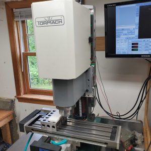
After the requisite CAM work to turn the 3D design into into G-Code for the CNC machine, I churned out a plastic prototype of the part to check fit. It was perfect as designed, which is probably a testament to the power of making paper models before cutting any real materials. I was anticipating that I’d need to order some aluminum stock, but when I woke up the next day I decided I’d make the part out of the material I had on hand, which just happened to be a huge chunk of 1.5″ x 3.5″ x 10″ 2024-T351 aluminum. With some judicious use of my band saw before and during the machining process, I was able to make reasonable use of the material, and actually improved the fixturing situation because I had so much extra material to hold in the vise to for the first set of operations.
The metal part fit just as well as the plastic one did, so I pushed the project over the finish line by powder coating the adapter in a textured black finish.
Hi Dude.
I want to know if you are selling the rear disc brake caliper mount for a Specialized Hardrock Sport 2014 size XL (21).
The bike has not the mounting holes on the rear wheel.
Thanks in advance.
I need one of these. Where can I get one?