Unfortunately, back in October, I discovered that my level of conversion kit for my mill did not include the hardware for home sensors for each axis. Everything was there, but for a few small brackets and mounting blocks, and the actual optical sensors themselves. I asked whether the company would simply send me the CAD drawings for those small parts, but they wouldn’t for intellectual property reasons. I suppose it’s fair, but still frustrating.
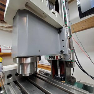
So, since then, I’ve been manually homing the machine. It’s annoying, and has to be done each time I start it up. I figured I would be a pain in the neck at best to add the homing sensors for the X and Y axes, since I needed the machine apart to conveniently get in to take measurements, yet I needed it together to know where the “fingers” of the interrupters landed exactly. Not to mention, I needed the machine together to actually machine the parts!
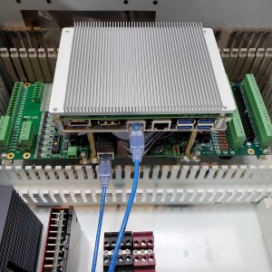
Since getting the shop set back up, I’ve been trying to think about and tackle a lot of little projects to get things operating better. I’ve been working on designing my own electronics breakout board (more in a later post), and I’d just included the homing sensors. Needing a break from schematic/PCB work, I decided tonight would be a good night to start tackling the homing sensor mounting.
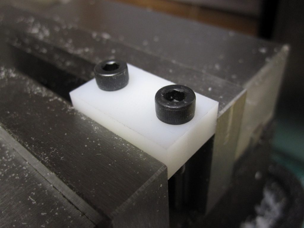
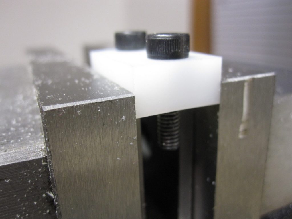
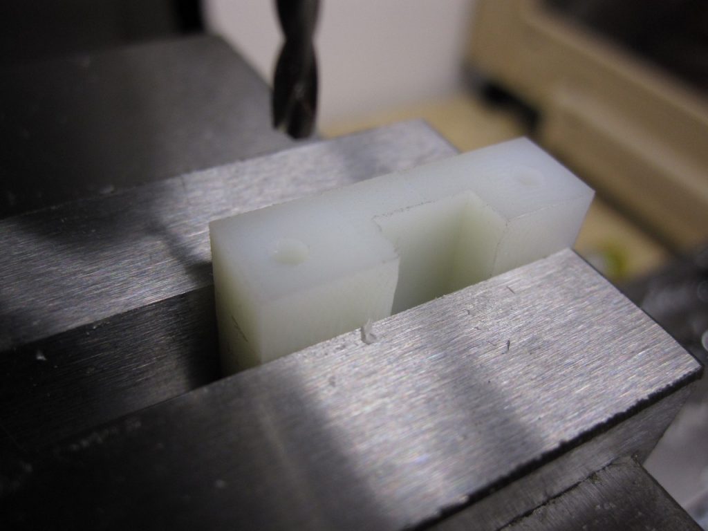
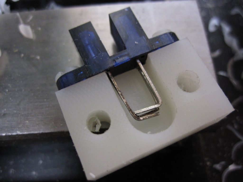
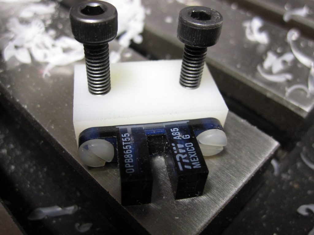
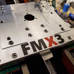
I could just reach up into the X endcap enough to take some rough measurements of the bolt spacing. After a couple of test holes in a scrap piece, I determined the proper spacing of the mounting. I then experimentally determined where the “finger” intercepts the optical interrupter. Doing some old-school PAD (paper-aided design), I quickly sketched up what I needed. I rough cut up a piece of nylon and went to town on it, running the mill in a mix of manual jog mode and simple G-Code commands. It’s a lot like manual milling with a DRO, just easier and faster. Once I get my pendant built, I think it’s going to be a very enjoyable way to work.
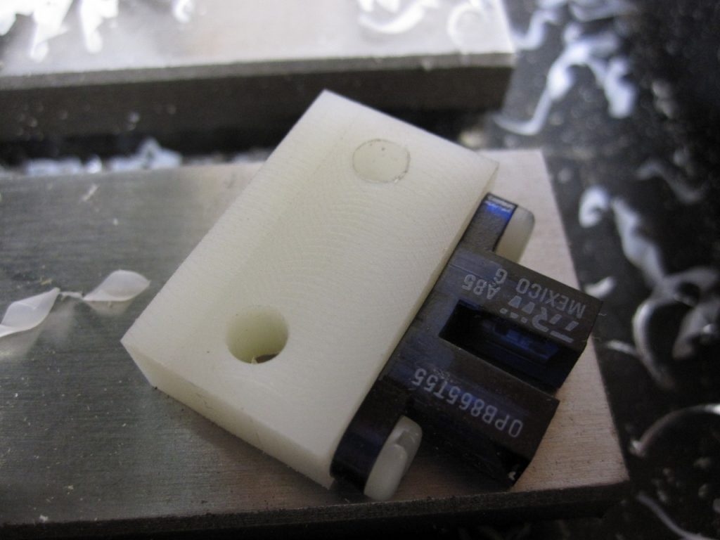
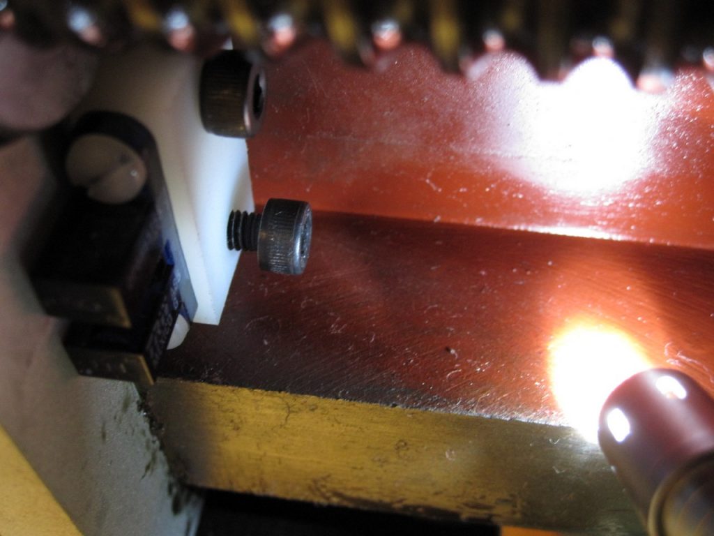
The mount fits perfectly on the X axis. I was hoping it would also work for the Y, but the spacing appears to be different, so I’ll have to make a new block for that next.