 I’ve completed the design and layout for another PC board, all part of the CNC milling machine electronics cleanup project. This one is a nicer version of the isolated PWM to +/-10VDC output circuit, which I had prototyped on perfboard a couple weeks ago. This circuit is used to drive a fancy KBMG-212D DC motor driver that I scored off of Ebay, and replaces the junky controller that runs the spindle of the milling machine.
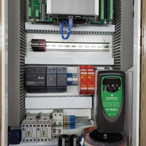
The circuit allows the controlling PC to control spindle speed and direction by outputting three signals. The first two are a “bipolar” PWM signal – one signal is active when the spindle speed value is negative, and the other is active when it’s positive. The other output is simply an enable output that turns the spindle on and off. The whole circuit has to be isolated because the DC motor drive is at a high voltage potential with respect to ground, and direct connection to electronics connected to a PC would make “exciting” things happen. It’s annoying that they don’t just include some isolation on the motor drive, but it seems to be common practice not to.
The circuit is fairly simple. An isolated DC-DC converter brick is used to generate +/-12V rails from 9-18VDC input. Schmitt output optisolators are used to isolate the PC control signals from the rest of the circuit. On the isolated side, the PWM signals are each filtered with a simple R-C filter and buffered by an op-amp follower circuit. The “negative” filtered PWM goes through another op amp in inverting configuration to flip the signal around. Finally, the “positive” buffered/filtered PWM is mixed with the output of the inverting op amp to add in the “negative” signal. A couple of trimmers are used to adjust offsets.
The prototype design isn’t perfect, especially in terms of accuracy, but since I’m planning to put the spindle speed into a servo loop controlled by EMC, I don’t think it will matter very much. I chalk it up mostly to my rusty skills and lack of experience doing analog design. I did a nice compact PCB layout which stuffs components onto both sides, and is intended to plug directly into the control terminal block on the motor drive. I sent it off to the DorkBot guy, and it cost a whopping $16.25 to have three of them made. For small board sizes, it’s just incredible to get professional boards done for this kind of price.
The actual size is a bit smaller than a business card. Here’s a picture of the artwork: red is the top side, blue is the bottom side.

Please note: I have removed the schematic because it really needs some changes! I will fix the design and post it when it’s done.

Did you ever redo the schematic for the KBMG-212D? I am planning on using the drive on a Emco Compact 5 CNC upgrade and yours is the only controller that I’ve found that does bi-directional control!
Hello, your KBMG interface is exactly what I am looking for (I am upgrading a small CNC lathe). Any chance of seeing the schematic? If you have not updated it a copy of the old schematic and comments on what you think is wrong would be welcome.
Regards,
Edward
Edward,
Unfortunately I haven’t fixed this design yet. I did some ugly software workarounds in my CNC config to make it behave “well enough” in the forward direction, but the design is fundamentally flawed and I would not recommend it.
I don’t know when I’ll get around to redesigning it, but I will definitely post it here when I do.
Thanks for the response. I have decided to try an approach based on pico system’s spindle DAC driven by their FPGA stepper controller.
Edward