I’ve been slowly working to model the components that go into the CNC milling machine electronics package, and fitting them into an off-the-shelf rack mount enclosure. I think I’m finally settling in on a layout that will work, though I need to put some additional thought into thermal design as there are some components which dissipate some heat.
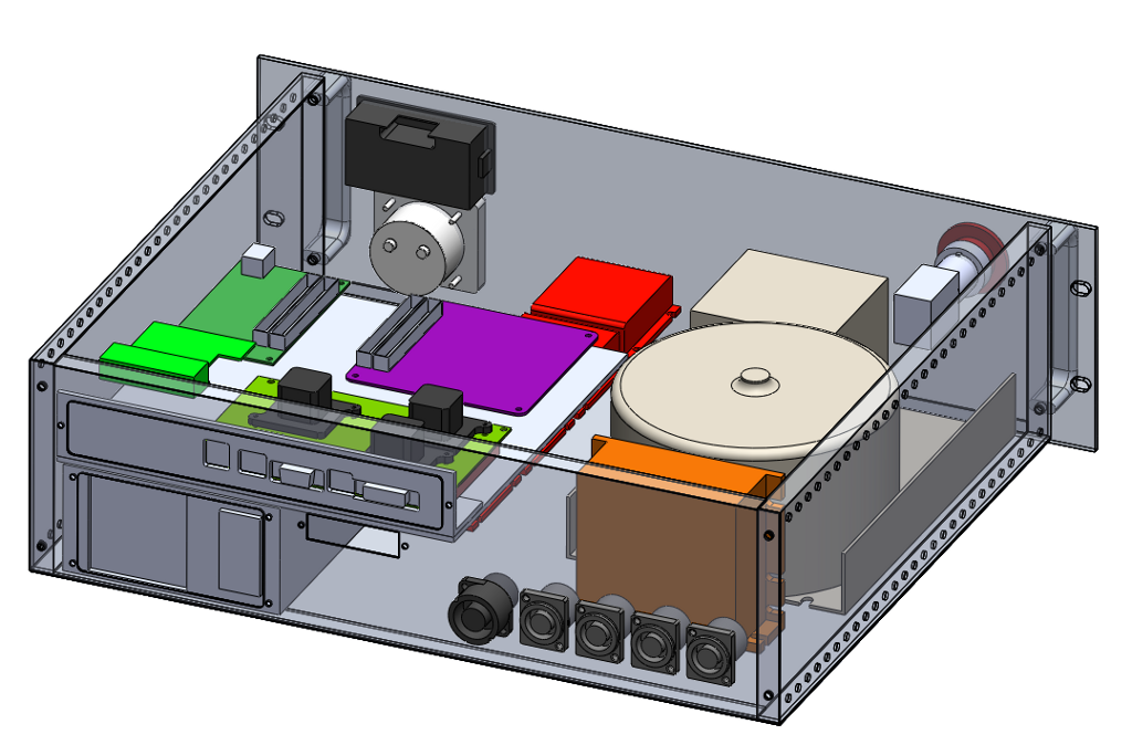
The front panel has a digital DC voltmeter and an analog ammeter, along with a big chunky emergency stop switch. The stepper drives (shown in red) will be located in the middle bottom of the enclosure. The DC motor driver for the spindle (orange) stands vertically near the rear of the case. The huge linear power supply (beige, with the big toroid) sits off to one side on the bottom. A small PC power supply (gray) rounds out the items on the “floor” of the enclosure.
The electronics (green and purple boards) are all mounted on a plate which sits in the upper part of the case, with the connectors for the 3.5″ PC motherboard poking out the back through a plate. The adaptable plate is in case I change motherboards in the future – it’s a lot easier to make a small plate than to remake the whole rear panel of the enclosure. Under that plate are the cutouts for the PC power supply, and the low voltage signal connection to the milling machine, which carries sensor signals. Rounding out the rear panel are four connectors for the stepper motors, and a single connector for the spindle motor.
It’s starting to come together, hopefully I’ll be able to wrap up the design work soon and actually start making some parts!
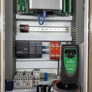
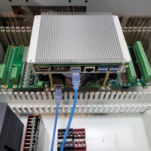
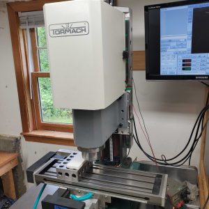

Great work on your controller layout.
Quick question, what sort of latency numbers are you getting from your 3.5″ single board PC?
Would you mind sharing the specs on the unit that you’re using?
Thanks a million,
Ken