I mainly considered two approaches to mounting rails to the column.
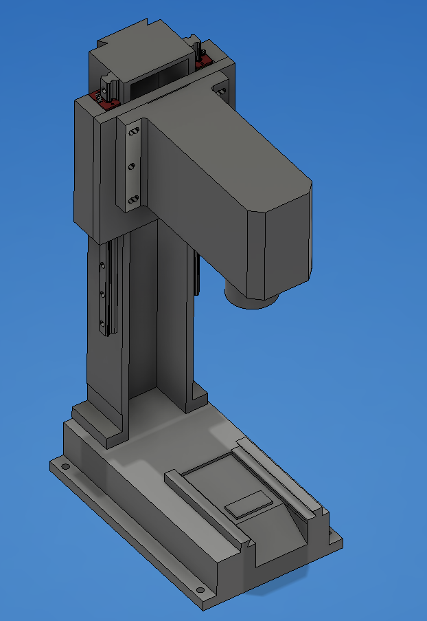
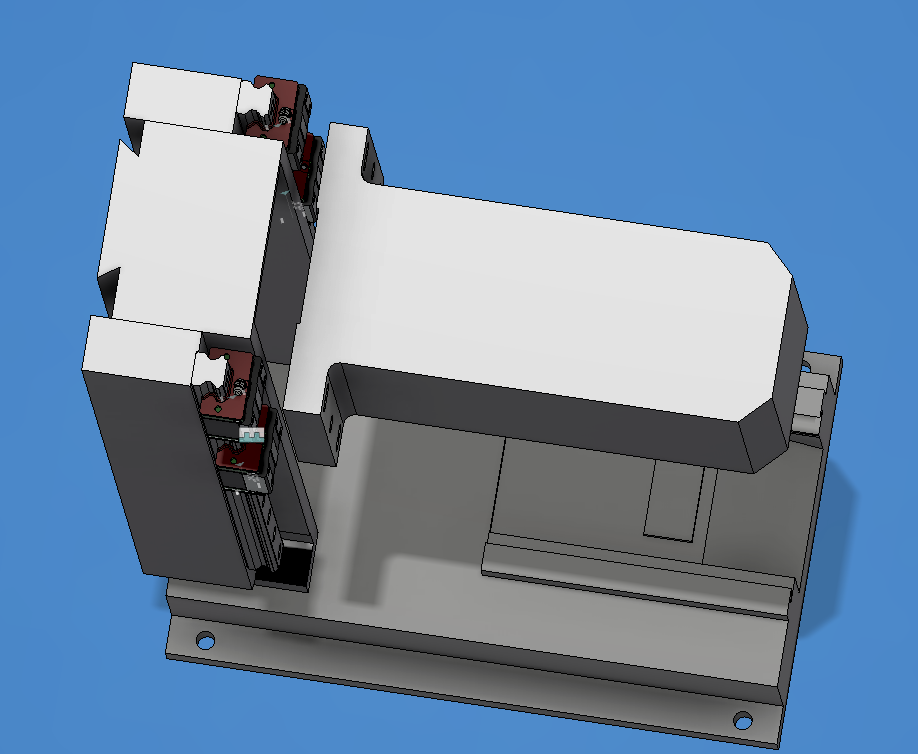
Approach 1 – add some kind of additional side supports to the existing column and mount the rails to the supports. A simple plate would be all that’s needed to mount the head to the blocks.
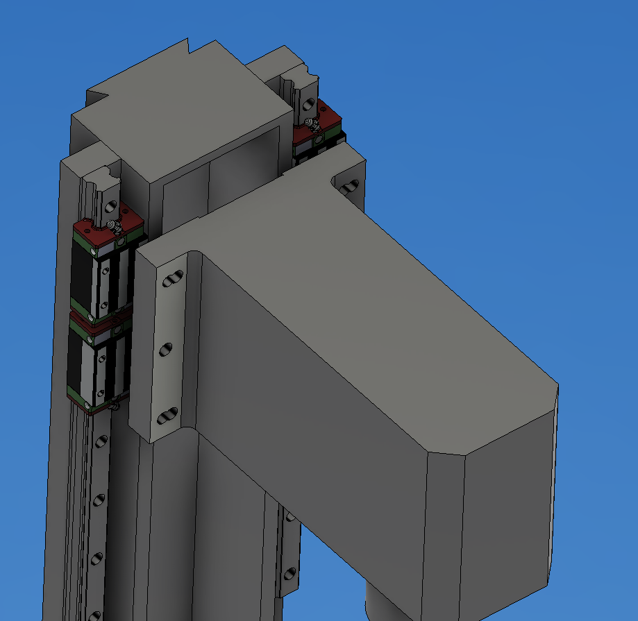
Approach 2 – mount the rails directly to the column and build a more complex saddle assembly to attach the head to the blocks. This appeared to use less material overall, but ultimately the headache of aligning the linear rails in this orientation steered me away from it.
I spent some time debating using steel vs aluminum for the added supports. After searching for drops from metal vendors, I ultimately settled on using 2024 aluminum rather than 1018 steel. Some compromises here obviously – aluminum has a significantly different coefficient of expansion than the cast iron, for one. And it’s not as easy to do traditional scraping to dial in the rail mounting surfaces in aluminum vs steel. But availability, weight, shipping/transport cost, and ease of cutting and machining all won out for me. I figure that it’s a low precision hobby machine – and all of the other conversion parts are already made out of aluminum. Any thermal expansion problems I create are likely to be overshadowed by all of the other issues the machine will continue to have even after fixing the Z axis.
Based on what materials were readily available as drops from the metal yard, I ended up going with significantly larger dimension material for the side supports than the initial sketch above – settling on 1.5″ x 2.5″ bar stock.
This approach might add some rigidity to the upper part of the column (especially if I can partially close in the front side) – but it’s limited by the weak bottom section where I needed to allow room for the original bolts to attach to the base. I have some things I’d like to explore that might help with rigidity in that area – basically some stiffening plates that would mount on the back of the new column, and potentially attach to the base at some newly created mounting points.