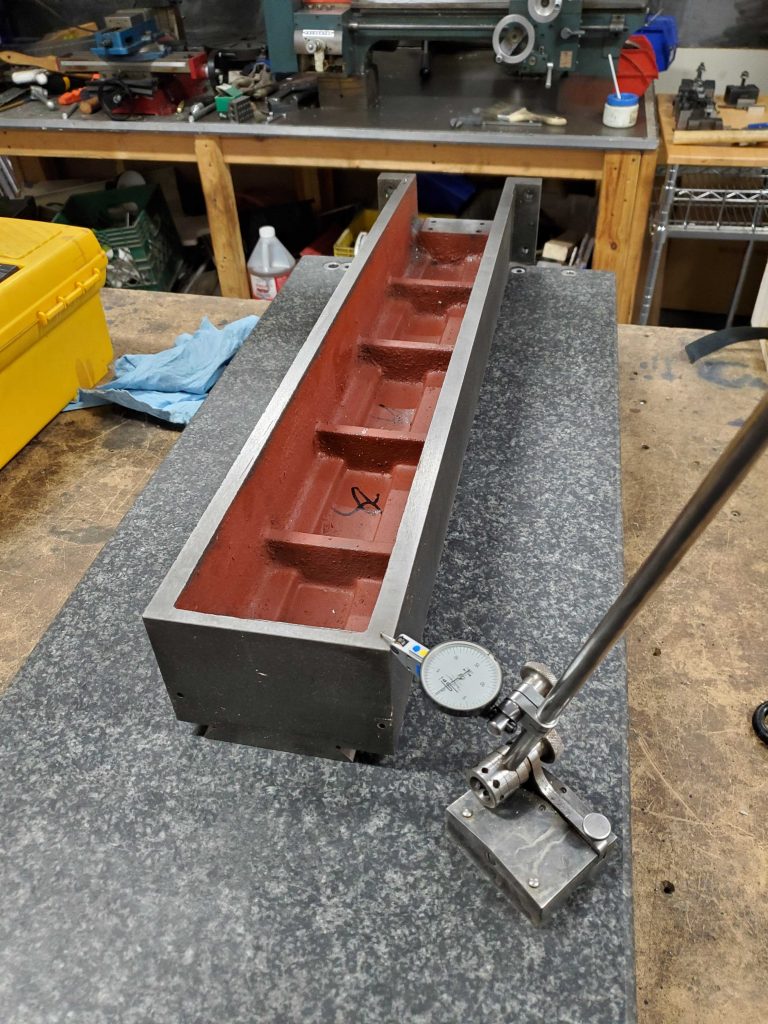
For extra security, I decided to epoxy the side bars to the column so they would not move. I figured the epoxy would also help fill in the troughs of the roughly fly cut cast iron surface and provide a more solid connection. I just used JB Weld here, nothing exotic.
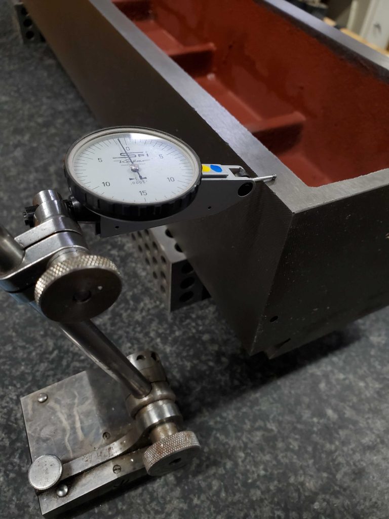
Once cured, I set up a 2-4-6 block with an indicator to slide along the front (formerly rear) reference surface of the column, so I could measure the position of the side bars relative to one another and find the high and low spots. Since I did the bolt hole work in a low-precision way with traditional layout, transfer punches, and a drill press, I knew it would not be that precise. But I also knew the linear rail surfaces would be machined for flatness and square. I used these measurements to gauge how much I needed to machine off to make both rail mounting surfaces parallel to the reference and with each other.
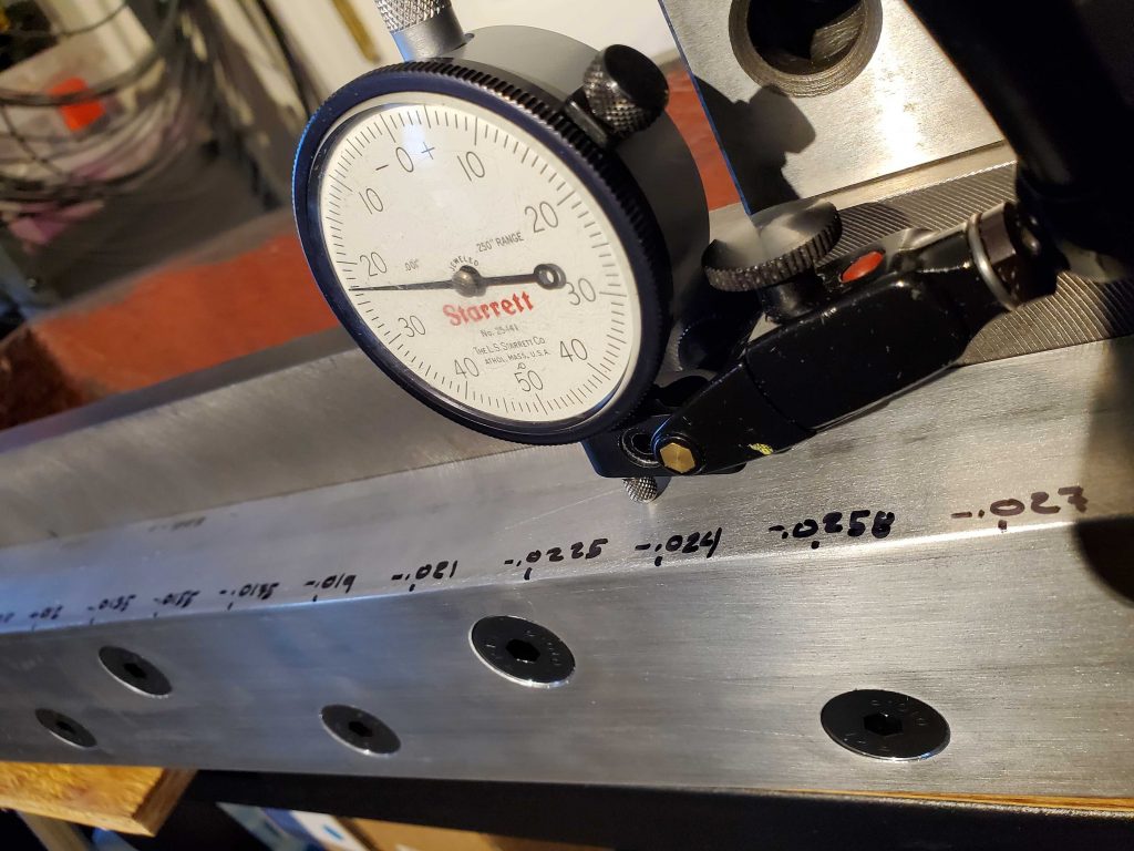
Early on, I had done some measuring of the column on a granite surface plate and was able to confirm that the original precision ground surfaces on the front and back of the column were in fact parallel and true within reason. One corner had a slight dip, but clearly these surfaces had been machined and ground in the original setup to cut the dovetails. Years ago I had confirmed that the column was relatively square to the Z travel within reason, so I was able to use these ground surfaces as references for setup and machining.
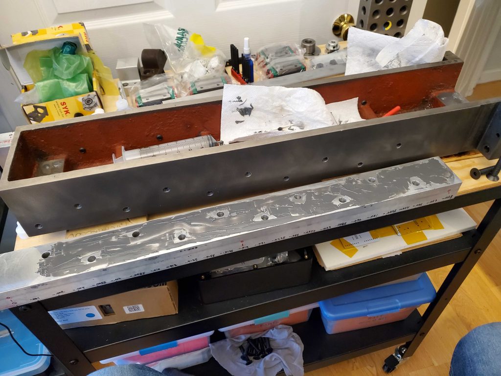
I set up on the Bridgeport and machined clearances on the back side so I would be able to flip the column and support it on 1-2-3 blocks using the original precision ground dovetail surfaces. After mounting the side bars, they protruded rearward beyond the precision surface, so this needed a quick fix. While I was at it, I put in some holes for the possibility of future attempts to make the column more rigid.
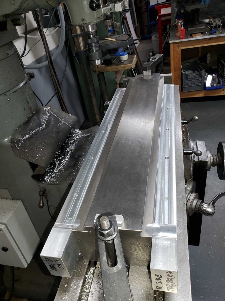
One “gotcha” is that the X travel on our Bridgeport is nominally only 24″ (610mm), limited in part by the motor for the ProtoTrak setup. I chose 640mm linear rails, and the aluminum side bars are even longer still. So it’s not possible to mill the whole back side for clearance in a single setup.
Thankfully after doing this operation, I discovered that it’s possible to squeeze about 26″ of travel out of the X axis with care. And the 1″ diameter end mill gets some additional clearance at the two ends. That was a relief, as it would make the critical machining for the linear rails much more simple.