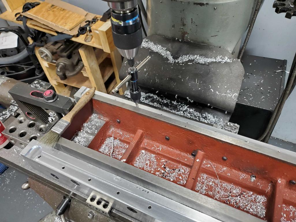
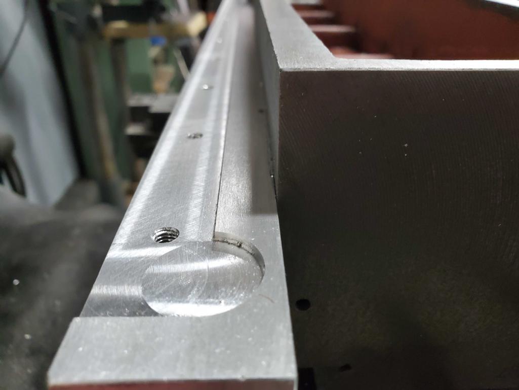
Now on to the critical milling to create the mounting surfaces and reference edges for the linear rails.
First thing in the morning, I spent a ton of time tramming and re-tramming the head of the Bridgeport to get it as close as I could within the limits of my measuring tools, skills and patience. Once that was done, it took quite a while to get the column positioned on the bed of the Bridgeport in the right spot so I could both securely clamp it down and also access everything that needed to be milled in one setup. Our Bridgeport only has a 42″ table so this was a bit trickier than it sounds.
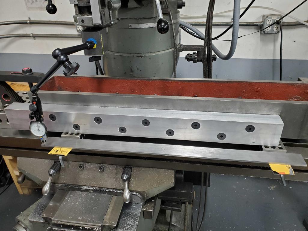
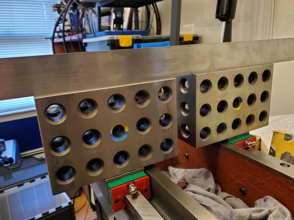
Of course, it also had to be set up with the column reference edge square to the X axis travel. I used a combination of 1-2-3 blocks and my 24 inch straight edge to “project” the ground dovetail surface out so I could run a DTI along.
I must have spent 3-4 hours working on the setup, but it’s certainly the most critical part. The actual milling and drilling is fairly easy once the setup is done right. I was so focused on the task that I didn’t snap many photos during the process.
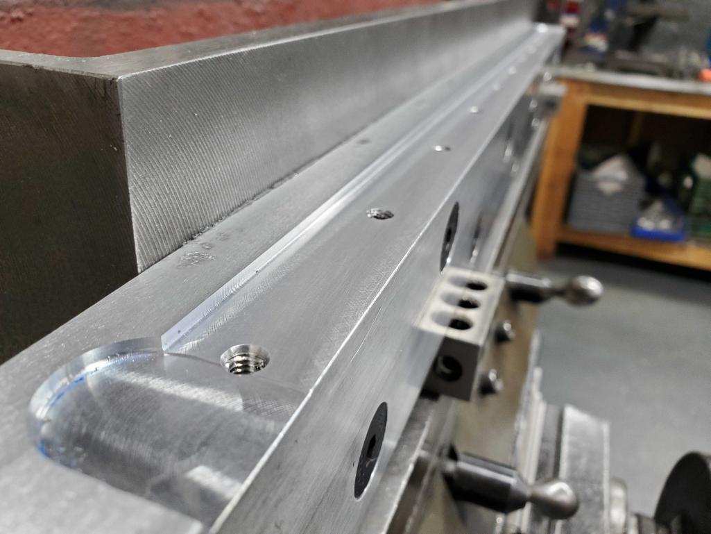
And now for an exciting moment – test fitting the linear rails, and doing some spot checks for flatness and coplanarity.
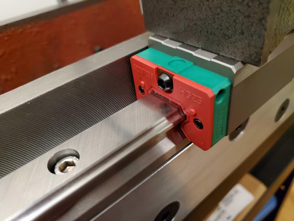
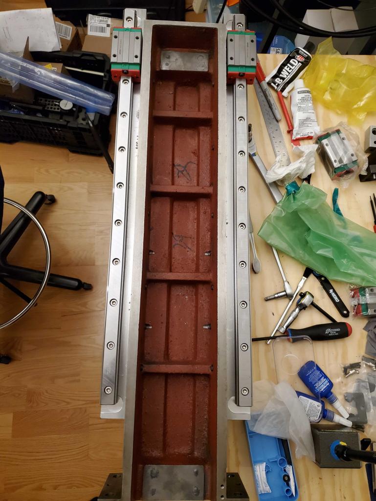
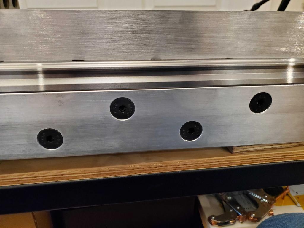
I did an initial mounting of the rails to check for parallel when using the two reference edges that I milled.